TAB DESIGN FOR FRONT SUSPENSION
overview
.png)
.png)
.png)
This project consisted of designing a tab that will allow a connection between the chassis and the suspension. A strong, durable tab must be considered to be able to hold up the weight of the suspension as well fulfill safety requirements. The old design consisted of a bolt and screw system as explored this design can be improved because a bolt and screw design may pose future failure risks. This encouraged the design of a direct weldment of a tab and the chassis. The design created are two tabs welded together and will be welded directly to the chassis. FEA simulation was done on the tab part to ensure the part itself will not fail in an impact. The results show a minimal deformation where it should not interfere with the suspension. The part passed all test except for the the side front face force. However, through discussion it was concluded that the tab design can pass because of how the tab is designed, a failure at the corner should not effect the rest of the structural design. The next steps taken will be to minimize the angel of the edge for the force to be able to disperse more throughout the tab in an event of a impact/force to ensure all FEA tests are passed.
.png)
_edited.png)
PREVIOUS DESIGN
The previous design consisted of a tabbing system that was directly mounted with a bolt and screw onto the chassis frame. The old tabbing was desirable for its ability to be manufactured easily and can be ordered in bulk. However, with a bolt and screw attachment this can create unnecessary friction and produces another point where the chassis can fail. If the screw loosened, this may cause a danger for the suspension to fall off and be detached from the chassis. Although this is an unlikely situation, with a bolt and a screw, it can overall lead to more weight and extra forces attached to the chassis.
Therefore, the goal for the 2018-2019 car was to redesign the tabbing to:
1. Reduce material and weight
2. Reduce points of failure and possible friction
.png)
DESIGN ITERATION #1
With our chassis considered as a space frame, we have decided to weld the tabbing directly to the frame. With some research, welded tabs have less chance for failure because there are less 'air gaps' [1]. They do tend to be slightly more expensive; however, with reducing on many weight components from the roll cage and the frame, a stronger attachment of the suspension with the frame is desirable.

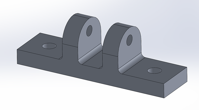
The first iteration of design consist of one tab that would be placed next to another one, allowing them to be directly welded into position onto the frame.
Concern: the position of the tabs must be perfectly aligned with each other. Manufacturing may be difficult because the angles of the parallel tabs must be exactly aligned or else the suspension will be unable to fit/screw perfectly between the tabs. As well, there are many weld points to considered, increasing points of failure and manufacturing.
DESIGN ITERATION #2
The second iteration of the design was inspired by how the McMaster Baja Car Team designed their tabbing. They have a background in welding their tabs with their frame. The Baja Car experiences very rough environments, so with that in mind, their design for the tab proves to be very durable and can maintain in shape during large impacts. With this strong attachment in mind, the drawing on the right is similarly to what Baja Car team uses. A square stock with two tabs that are designed together so that does guarantee a strong and symmetrical attachment.

DESIGN ITERATION #2 - On solidworks
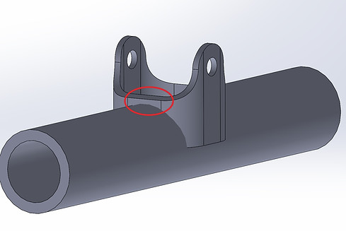
The tab drawing from Design Iteration #2 was designed on SolidWorks. I made a custom profile of the smallest possible square stock size that our manufacturer can print which is 1x1x0.065 in. Our tubing size used for the chassis is SCH 40, 0.5". This may pose a concern because the square tabbing will not fit perfectly onto the pipe.
A tube structural member was added as a stationary base to act as a building point for the tab. A Key Hole shape was sketched onto the design.
.png)


There are two elements that I want to highlight.
1. The distance between the edge and the pipe
2. The gap between the tab and the pipe
When discussing my design with my team captain, I was able to get some feedback about how the distance between the edge of the tab and the pipe in my design may pose a problem. The distance is minimal. There may not be enough support on the side as the weldment would be very close to the edge. This leads to the second issue with the gap between the square stock and pipe. The space allows air to travel through. This may increase the chances of failure because if there was an impact, the force could travel within the gap causing internal force and forcing the tab to fail.
To fix this potential problem, I decided to increase the depth with the edge to the pipe to increase more side support before testing the FEA.
DESIGN ITERATION #3
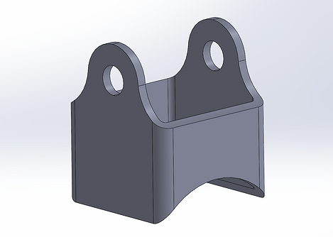
The depth of the side was changed to allow a larger support on the side to reduce possible failure from the gap between the square stock and the pipe. The tube was eventually removed ready to be assembled with the chassis space frame for FEA testing.
_edited.png)
_edited.png)
Change in chassis space frame design
The current design of the chassis space frame was changed where an initial pipe used of SCH 40 0.5" was changed to SCH 40 1.5". With this change, the design was changed to use a stock size of 1.5x1.5x0.1 in.
_edited.png)
_edited.png)
attachment of tab to chassis frame
_edited.png)
The placement for the tabbing was determined by the dimensions from the suspension. This placement will be fixed. The following dimensions of the tab placement are listed below:
.png)

.png)
.png)
Whole chassis space frame with roll cage and front suspension cage
Assume mass: 250kg
The image to the right is a cutout of just the front suspension cage.
The initial consideration of what type of FEA should be done was thought out. There were a few options for FEA. 1. Test on the whole chassis with tab 2. Test on just the suspension cage with tab 3. Test on just the tab part file itself.
It was concluded that Test 3 will be done. This decision was made off from how I want to see if the tabbing part itself will fail.
FEA analysis on Tab Part
To determine how successful the designed tab is and if it will qualify through the safety requirements a FEA analysis will be done on the tab. The decision of applying a static force on the tab to see if the model itself will fail will determine the successfulness of the design. The effects on force will have determine if the tabbing fulfills the safety requirements and if it will be durable enough to maintain the weight from the suspension to the space frame. The test will give a magnified look into how it will interact with the whole space frame once manufactured.
Requirements:
- Able to withstand 5g of static force in all directions
Specification:
Mass of chassis = approx. 50kg
Force applied to tab = 5*9.81m/s^2*50kg = 2452.5N
Material = AISI 4130 Steel, annealed at 865C
Ultimate Yield Strength = 4.6E8N/m^2
.png)
Upwards Force:
-
Mostly blue region on the bottom
-
Stress increases further up the tab
-
A lot of green region showing some deformation around the round section showing a mid-range impact
-
The maximum stress is centered at the hole for the suspension to attach to
-
Maximum stress is at 2.703E8 N/m^2
-
Max. Stress < Ultimate Yield Strength
-
Test Passed
-
.png)
Sideways Force:
-
Mostly blue region on the whole tab, except for the face of impact
-
High green concentrated result, showing mid-size deformation effect
-
Maximum stress centered on the bottom edge of the face
-
Maximum stress is at 2.550E8 N/m^2
-
Max. Stress < Ultimate Yield Strength
-
Test Passed
-
.png)
Downwards Force:
-
More green region indicating a higher impact effect on the tab
-
Mid range impact
-
Same as the upwards force FEA, there is a high force stress concentrated at the hole
-
The deformation is inwards
-
Maximum stress is at 1.854E8 N/m^2
-
Max. Stress < Ultimate Yield Strength
-
Test Passed
-
.png)
Second Sideways Force:
-
Mostly blue region among the tab
-
A concentrated stress on the edges of the tab - indicated by the green, yellow and red
-
This test failed as the maximum stress is at 8.902E8 N/m^2
-
Max. Stress > Ultimate Yield Strength
-
Test Failed
-
Although this is a failed test, this should not be the biggest concern as in an impact, the tab will not be getting direct impact towards the whole face.
.png)
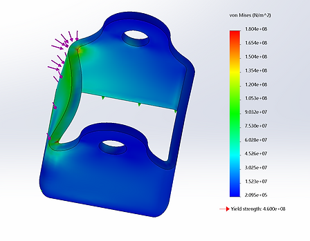
Diagonal and Top Force:
-
Mostly blue indication through whole tab
-
There is a focused stress around the impact area, shown by green
-
There is significant amount of deformation, however, it should not effect the attachment to the suspension
-
Maximum stress is at 1.804E8 N/m^2
-
Max. Stress < Ultimate Yield Strength
-
Test Passed
-

Deformation analysis of the tab shows that all tests show a minimal deformation of less than 1mm. The failed test of sidways 2 shown in the force impact stress result, shows the largest deformation; however still less than 1mm. The smallest deformation was during the diagonal and top impact simulation.
DISCUSSION AND SUMMARY OF FEA
By analyzing the FEA simulation of each of the the different impact, overall, it can be concluded that the tab has passed successfully. Although the second sideways force simulation showed a failed test; realistically, in an impact the full 2452.5N of force is highly unlikely to be experienced by the tab itself. The point of failure is indicated by the edge, where it would only tear the edges a bit, however below the point of highest stress, is blue indicating a more minimal effect. In other words, even if the edge fails, the depth of the tab can still hold up the tab structurally. The deformation values indicate a very minimal impact as it less than 1mm. In summary, the tab will be able to maintain in shape as well support the suspension proven through the set of the FEA images.
Next Steps:
- The tab design can be further improved by manipulating the design of how the edge meets up. The curvature meeting the side of the tab with the round hole part can be improved with a less angled changed which may improve the FEA simulation as the force would be more equally distributed among the tab. The next goal would be to pass all the FEA tests for a guaranteed confirmation that the tab will not fail during impact or the force from the suspension.
.png)


