ROLL CAGE: DESIGN ITERATIONS
overview
The primary role of a vehicle's roll cage is to provide the passenger safety in an event of a rollover or crash. It can be described as a protective frame that is built with the frame of the car around the passenger compartment. The roll cage design most often consist of welded roll bars that are made with a specific type of metal.
Goal: Redesign the Roll Cage for the 2018-2019 Solar Car
The roll cage of the current solar car will be attached to the chassis. Indicated in the red circle in Figure 2 is where the roll cage will be placed to protect the driver in an event of a roll-over or impact.
.png)
_edited.png)
Three main goals were considered: Weight, Safety, Material. Over three design stages were taken to improve the current design of the roll cage to be implemented with the chassis
Technical Skills Developed: SolidWorks (3D Modeling)
Background

Requirements
-
Impact:
-
Withstand 5g load in all directions
-
-
Other requirements
-
Pelvis, abdomen, thorax and shoulders must be covered with energy absorbing material at least 50mm thick with compressive strength 500-1000 kPa
-
Cloth stretched around roll cage is clear of full free range of motion including helmet
-
50mm clearance in all directions
-
30mm clearance between occupant helmet and patting
-
The roll cage of the current solar car will be attached to the chassis. Indicated in the red circle is where the roll cage will be placed to protect the driver in an event of a roll-over or impact.
analyzing previous design
Analyzing the previous design of the roll cage; there are a few key elements to highlight:
1. Two roll bar sections
These two-roll bar consist of a concave down hoop with a linear support on the back. Additionally, the sides are attached two beams. One beam is a fully extruded rectangular prism where the other is a L-bar. There is also a corner attachment on the back.
2. Material
AISI 4130 Steel, normalized at 870
3. Weight
13661.07g
.png)
Requirements
There are 3 factors that I thought was the most important to consider when redesigning the roll cage:
-
Weight
-
Safety
-
Material
Weight:
The previous design involves two roll bars; one placed in the front having an angle of approximately 8-degrees to the beam and one placed on the back with an upward 90-degree angle. Improvements: Two hoops include a large level of weight onto the car which is not ideal. Two bars increase the level of safety to protect the driver’s body and legs; however, there could possibly be another solution with just one hoop bar to decrease cost and weight.
Safety:
The previous design has asymmetric parts: one side is a rectangular prism attachment where the other side is a L-bar attachment. The attachments to the chassis can be manipulated and a solution can be found to reduce weight, cost and stability.
Material:
The previous design involves two roll bars; one placed in the front having an angle of approximately 8-degrees to the beam and one placed on the back with an upward 90-degree angle. Improvements: Two hoops include a large level of weight onto the car which is not ideal. Two bars increase the level of safety to protect the driver’s body and legs; however, there could possibly be another solution with just one hoop bar to decrease cost and weight.
Brainstorm
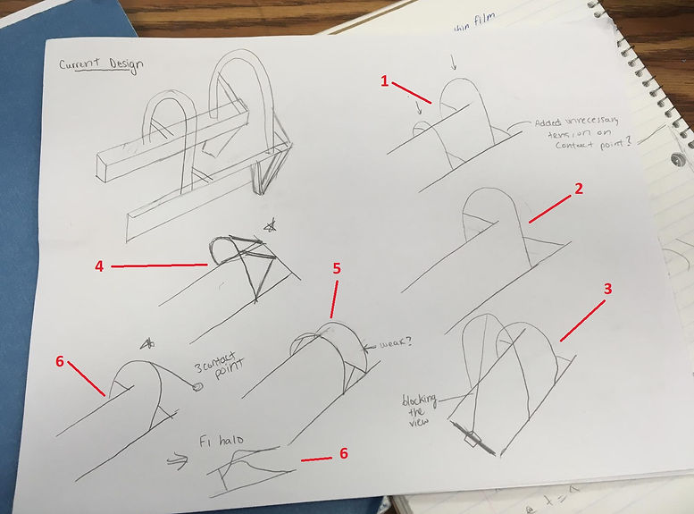
1 - The first option consists of the same design as the previous design with symmetrical elements such as the roll bars placed at the same angel with its supporting beams. However, something to consider is adding additional supports on the roll bar would it add unnecessary tension on the contact point?
2- The second option consist of just one bar; however, the concern for this is if it would fully provide the passenger safety in an event of a roll over. The bar would be above the head; therefore, the area of protection is limited.
3- The third option idea spurted from research about the Stanford Solar Car [1]. Their design consisted of two roll bars where the taller roll bar has a supporting beam starting from the base of the roll cage. This will provide additional support to the roll bar so in an event in a crash the deformation would be minimized. This design was initially thought of the driver sitting towards the supporting beam; however, would not make too much sense because the beam would be blocking the view as well the back-roll bar would give too much support of the upper body as it is lower than the other bar. If we reverse the design, that would also not make too much sense because the supporting bar at the back may coincide with the seat and the driver’s head would not be supported as well as the smaller beam would add additional weight.
4 - This design consists of one roll bar but with vertical beams to bring the roll bar more forward where it can provide protection for the upper body but reached out front enough to provide protection on the lower body.
5- This consist of two roll bars that are close together where the seat would preferably be placed between the bar. However, an issue that may occur in this design is the back-roll bar may not be supported enough
6- The 3-contact point kind of roll cage was inspired by the roll cage on the race car F1 halo [2] which is known to be one of the safest race cars. Their roll cage involves a 3-contact point design where the side roll bars are curved leading to a singular point that reaches down to the base. Taking this design, the modification of the design consists of a third contact point consisting of a concave down loop bar with a supporting beam that is welded to the back. This design is similar to the 3rd idea but simplified to a more realistic design.
design iteration #1
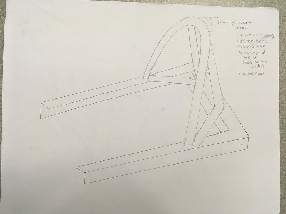
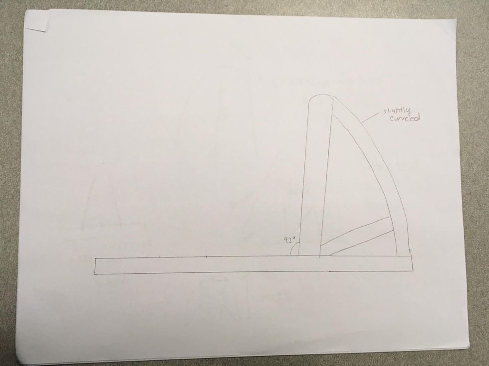


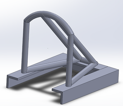
Design 4 and 6 from Figure 3 were the best possible designs to work from to give the roll cage a new look as well as improvements from previous design. Focusing on Design 4 first, initial design drawings and solid works CAD model was built
Overview:
This design consists of one roll bar with two vertical supporting bars welded to the top arch of the bar that welds to two horizontal bars. The two vertical bars provide upwards support to the roll cage to help reduce deformation to the roll bar in an event of a roll over. The two horizontal bar provides extra support for the vertical bar and the bottom of the roll bar to not deform and provide a more structural support.
_edited.png)
Supporting Roll Bars:
The supporting bars on the top arc will be approximately 4 inches apart. This will help avoid buckling. Buckling is a type of instability failure where a compressive force causes a beam to bend sideways. Additionally, with two bars separated it allows the driver to look at blind spots and right behind. Like if the driver turns around the view shouldn’t be blocked.
It has a good back support to provide the driver with more protection. There is more than one point of contact; therefore it does not concentrate the force directly to one point.
Summary of Design #1:
From the last design a few points to reconsider:
-
There is a large concentrated stress at the corner of the roll bar. Adding other supports connecting to the cage may reduce the force to be concentrated at that point
-
There’s not much room for safety of passenger. Especially for the deformation of a top impact. This will create a large danger to the driver’s head as since the seat won’t fit into the roll cage itself which hinders the use of a roll cage.
In summary, some points to consider is adding an upwards lift at the back-supporting bars. This will allow the driver’s seat to be moved into the roll cage which will therefore allow the driver to be fully enclosed around the roll cage. As well as adding additional supports to disperse any concentrated force at a joint.
design iteration #2
_edited.png)
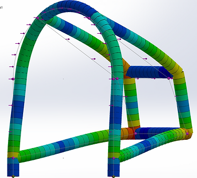
An upwards lift in the back-support bars were added. This lift consists of a rectangle-like shape for a direct 90 degrees vertical lift. This allows the roll cage to include more space internally allowing the seat to be immersed more into the cage.
From the FEA simulation, the high concentrated force in each simulation showed similar results from the first design showing that additional supporting beams may be needed or a more drastic change in the design must be prompted.
design iteration #3
This design stage consist of different modification of the original design
 1 - Single Contact Point Design |  2 - Two hoops connected by supporting bars design |  3 - Two hoops with additional supporting bars |
|---|---|---|
 4 - One hoop with elevated back and curved supporting bars |  5 - Two hoops with 3 connecting bars |  6 - One hoop with elevated back with many supporting beams |
 7 - One bar with elevated back and curved supporting bars with additional beams |
After two design iterations, I noticed the maximum yield strength data weren’t changing drastically. The similar results prompt me to work with another chassis team member where we decided to take the original design and modify a specific part and change it drastically. This involved over 7 design iterations with FEA to see what works and what doesn’t. The angles, how the supporting bars were placed, and the number of supporting bars were the changing factors. The figures above represent the different iteration designs that were made to help create the final design. This involved taking different elements of each iteration that gave successful results and putting those elements together.
Final Design
Summary of Final Design:
-
One Hoop Bar
-
Two supporting bars diverging from the top point and curving down towards the back
-
Helps spread the forces outwards from a single concentrated point
-
Provides the driver with additional head space, allowing to be able to be fully enclosed by the roll cage
-
-
3 supporting bars to provide structural supports
-
Diverges the force from a concentrated point
-
Adds structure to help avoid deformity from a top or front impact
-
-
3 side bars on each side to provide the curved bars structure support from underneath
-
Provides structure to avoid deformity from the backwards impact
-
In summary, a mixture between Figure 18, 20 and 21 were put into consideration when finalizing the design. The rounded back curved bars provide the roll cage with a stronger structure because a curved shape avoids the any concentrated force at a single force -- it spreads the force throughout the curved area. It was found that removing the bottom base made no impact to the mechanical properties of the model; removing the base saved material which lowers cost and weight.
_edited.png)
Summary of design iterations of roll cage
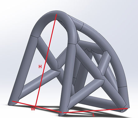

Designing the roll cage allowed me to experience the design process of redesigning a part. There are always many elements to consider. The beginning step is always to analyze old designs and seeing what can be improved and what elements are crucial to the model. Being able to think flexibility and take different brainstorming ideas together will help optimize the design. Using FEA helped simulate the roll cage in an event of a crash or roll-over to predict how the roll cage would react to the certain impact. The simulation allows us to really understand what is happening and why a certain part is experiencing plastic deformation.
Previously stated, the goals in the redesigning project was to consider the material and weight. It was researched from a team member that using the AISI 4130 without heat treatment would still be a good material to use. Using a heat-treated alloy or another material wouldn’t make a large impact to the results. Additionally, the new design of the roll cage is a lot lighter than the old one as it went from 13661.0g to 1660.0g. This may have been the impact of incorporating a one roll bar element and removing the bottom base. The one roll bar not only helped reduce the weight, but still fulfilled the safety requirements

Chassis with Roll Cage

Chassis with Roll Cage and driver

Chassis with Roll Cage